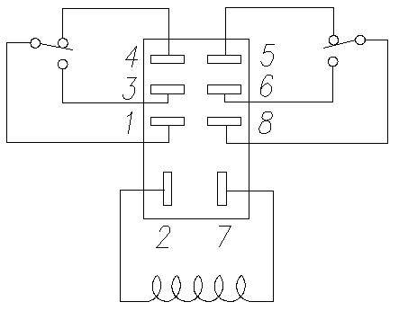
Ladder and wiring diagram using an 8 pin electrical relay to turn on and off lights.
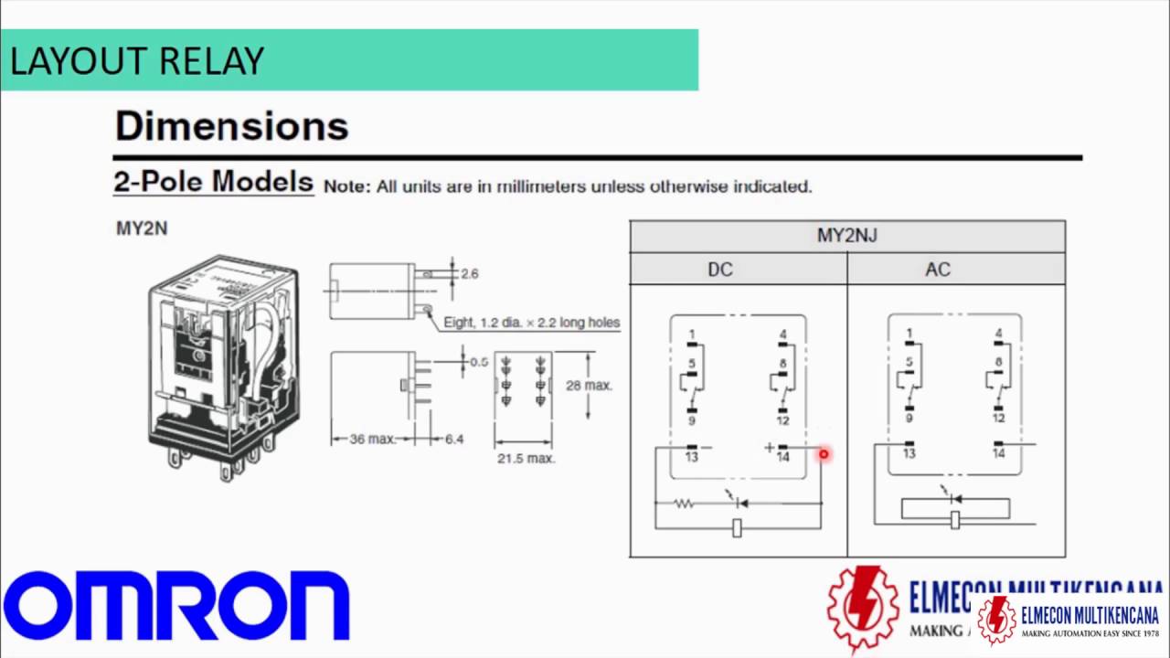
8 pin omron my2n relay wiring diagram.
Omron 8 pin relay wiring diagram wiring diagram is a simplified suitable pictorial representation of an electrical circuit.
Pins 8 6 as normally open pins 8 5 as normally closed.
Pins 8 5 as normally closed.
These guidelines will likely be easy to comprehend and implement.
12v 40a relay wiring diagram.
24v 8 pin relay wiring diagram.
The indicator is red for ac and green for.
Details about omron mk2p i ac 220v relay 8 pin 10a 250vac with pf083a socket base.
Wiring diagram arrives with numerous easy to follow wiring diagram instructions.
4 pin relay 4 pin relays use 2 pins 85 86 to control the coil and 2 pins 30 87 which switch power on a single circuit.
Normally open or normally closed.
For the dc models check the coil polarity when wiring and wire all connections correctly.
There are 2 types of 4 pin relay available.
It shows the components of the circuit as simplified shapes and the knack and signal friends in the midst of the devices.
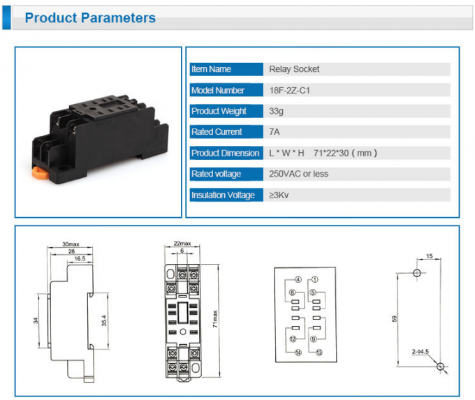
These relay are connected in a socket which is also called base.
Posts related to omron 8 pin relay wiring diagram.
A normally open relay will switch power on for a circuit when the coil is activated.
Relay 8 pin wiring diagram datasheet cross reference circuit and application notes in pdf format.
8 pin omron my2n relay wiring diagram.
Relays are devices making or breaking electric circuits by their output section driven by operational signal which is triggered by electric input signal con.
5 pin relay wiring diagram.
12v relay wiring diagram.
An ac model has coil disconnection self diagnosis.
8 pin relay wire diagram wiring schematic wiring diagram 8 pin relay wiring diagram.
My2 my2n my2 d my2n d2 my2 cr and my2n cr terminal arrangement in ternal connections bottom view standard models the coil has no polarity note.
3 pin flasher relay wiring diagram.
8 pin relay wiring.
Variety of omron h3ca a wiring diagram.
I hope this helps you.
8 pin relay wiring diagram.
This assumes a standard 8 pin relay.
It shows the components of the circuit as simplified shapes and the power and also signal connections between the tools.
The coil and pin numbers are always marked on the relay and or the base socket it plugs into.
It is meant to help each of the common consumer in building a correct method.
5 pin relay wiring diagram fan.
14 pin relay wiring.
When the normally open limit switch ls1 is flagged the motor control relay coil will be energized and will close the relay contact s 1 3 and 6 8.